Timer Project
The objective of the project was to create a timer module that could trigger
a relay multiple times at a predetermined interval. The timer would be
used for interval-timer photography, such as recording a 3D print to play
back in super fast motion. Although this project uses the timer to operate a
relay that is connected to a camera shutter release, it could instead
trigger a LED to signal an optical device, or trigger a shutter
directly. Currently the relay is external to the unit, but there is
space in the case for including an internal relay.
PARTS.
U1 Arduino Pro Mini. I chose the Pro over the Nano
because I do not expect to be re-programming it and the USB interface
could not be justified. The programming pins are accessible if needed.
L1 128x64 OLED display with I2C interface to display the settings and the
progress. Header pins and sockets to suit. This model OLED
uses a different colour for the top few rows, and the code takes advantage
of this.
SW1 Momentary SPDT switch for up/down control. Salvaged from an old CD
drive. Two single pole momentary switches could also be used, but
the 'rocker' style of this switch is very easy to use.
SW2 Momentary SPST switch for reset. Salvaged from somewhere.
SW3 SPST On/Off switch. Salvaged from the PCB of some old piece of gear.
D1 LED and matched R1 resistor (eg 220ohm).
Hookup wire and prototype board (see below).
Q1 Small NPN power transistor. (Eg 2N2222) and resistor as required for
the load to be driven (eg 1k)
B1 9v Battery with clip and leads.
3D printed case.
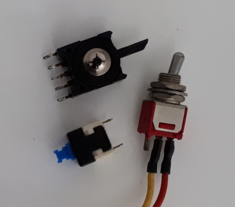 The
switches can be anything suitable, but the height needs to be considered if
they are all mounted at the same level on the prototype board. The
'rocker' style switch used for the up/down adjustment has five pins but only
three connections - each pair of outer pins is the same side of the
switch.
The OLED display is a common, easily available item. For this
project I mounted it using the header pins inserted into a matching header
socket mounted to the breadboard. These displays are also available with
an ISP interface - either would work for this project, but the extra speed
of ISP is not required. The display sits below the cutout in the lid
and is supported by the header pins and a small packing piece under the
substrate. I avoided a more solid mount because of the risk of fracturing
the delicate glass face plate.
The prototype board I used is marked 2-110 and is similar to this.
It is actually designed for the Pro module to straddle the centre row, but
as I am only using a few pins for the module it was easier to put it at the
bottom of the board and leave space for the other components at the top.
THE CIRCUIT
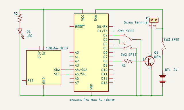 The 9v battery power is provided via the on/off
switch to VRaw of the Pro. Vcc from the Pro is wired to the
OLED. The grounds of both devices are tied to battery ground.
The up/down switch for setting the timer period is connected to data pins 2
and 3 (active low) and the start/stop button is connected to data pin 5
(active low). Output to the transistor and the relay is at data
pin 8 There is no particular reason for choosing these pins -
any data pins would work as well. The OLED is driven from the standard
UNO/Pro SDA and SCL pins.
ASSEMBLY
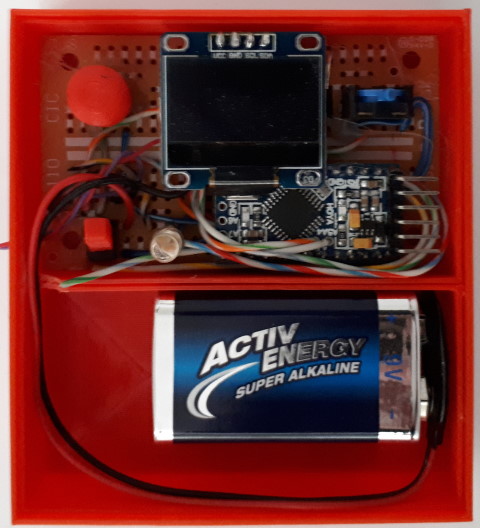 The
Pro has header pins soldered on two edges and for the programming pins, but
not across the fourth side as this would make things too crowded on the
prototype board. I soldered leads to the prototype boards before
soldering the Pro on, as with this particular board the traces to the header
pins are only available between the header rows. Although this makes things
a bit tricky it saves a lot of board space and is much easier than trying to
solder on the trace side of the board. I also soldered some leads to
some of the unused pin traces in case I wanted to add new features later
on. The hookup wire came from an old parallel printer cable.
This wire is easily tinned and soldered, the covering is very heat
resistant, it is quite flexible, and the multitude of colours means that the
wire can indicate the function of the connection, reducing the risk of
mistakes.
THE CASE
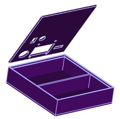 The case is a simple two-part assembly, with a lid that
sits down into the base without any attachment. The lid would be a good
candidate for a magnetic attachment. The base is divided into two
parts - one is a tight fit for the prototyping board and the other is a
large area for the battery. I did not divide this area because I might
want to install the relay, which currently swings freely at the end of a
wire, inside the case at some time in the future. Foam spacers can be used
to stop the battery sliding around. The relay lead exits the case
through a hole near the bottom left corner of the prototype board.
I printed knobs for the reset and power switches so
they would match the case, and added a small surround for the LED to make
it look a bit neater. I filled the mounting holes for the OLED with plugs,
after deciding that I did not want to screw the device down to the lid.
COMPLETED
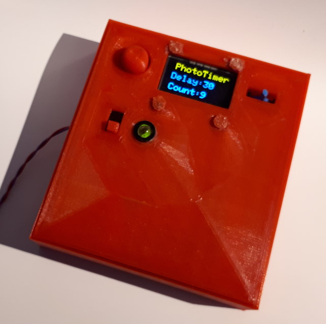 The completed unit, with the lid pushed down into the
base. When the unit is is turned on the interval between ticks can be
set using the momentary rocker switch - right to increase and left to
decrease. Timing is started and stopped with the large momentary
switch to the left of the display. If this is pressed when the timer is
running then the display is inverted to show that timing is paused.
The current interval and the number of ticks are displayed. If
start/stop is pressed again the count is cleared to 0 and timing starts.
CODE
The timer uses a timer library with interrupts. There
are several timer libraries available for the Arduino, so substituting a
different one would not be a problem. The interrupt-handling routine
breaks most of the rules for using interrupts, but as the time interval is
completely controlled by the code it doesn't create a problem. The timing
interval can be set from one second to 9999 seconds. To make this
possible with a simple user interface acceleration is used - each time the
interval is increased or decreased the rate of change is raised by a
factor of 1.2. So holding the switch in one direction or the other
gradually increases the rate at which the interval increases or
decreases. The full range of 1 to 9999 takes about 15s. If the
switch goes back to neutral the step is reset to 1, so that at any point
the interval can be set to an accuracy of 1s by briefly flicking the
switch.
Code is included to save the currently selected
interval to EEProm so that it can be retrieved at startup and set as the
default.
/**************************************************************************
Timer using OLED based on SSD1306 drivers
This sketch uses a 128x64 pixel display using I2C to communicate.
4 pins are required to interface.
Vcc --> +5v
Gnd --> Gnd
SCL --> A5
SDA --> A4
2-colour OLED has 16 lines of yellow and 48 lines of blue (pixel
lines are numbered 0 to 63).
Oled library is at:
https://adafruit.github.io/Adafruit_SSD1306/html/class_adafruit___s_s_d1306.html
Timer library is at:
http://www.doctormonk.com/2012/01/arduino-timer-library.html
**************************************************************************/
#include <SPI.h>
#include <Wire.h>
#include <Adafruit_GFX.h>
#include <Adafruit_SSD1306.h>
#include <Timer.h>
#include <EEPROM.h>
#define SCREEN_WIDTH 128 // OLED display width, in pixels
#define SCREEN_HEIGHT 64 // OLED display height, in pixels
// Declaration for an SSD1306 display connected to I2C (SDA, SCL pins)
#define OLED_RESET 4 // Reset pin # (or -1 if
sharing Arduino reset pin)
Adafruit_SSD1306 display(SCREEN_WIDTH, SCREEN_HEIGHT, &Wire,
OLED_RESET);
Timer t; // Create the timer instance.
long period;
int8_t tickEvent;
long count = 0;
String pMessage;
String cMessage;
const int buttonUpPin = 2; // the number of the
button pin for UP
const int buttonDnPin = 3; // the number of the
button pin for DOWN
const int buttonRsPin = 5; // the number of the
button pin for RESET
const int clickPin = 8; // then
number of the button pin for CLICK
int buttonUpState = 0; //
variable for reading the button UP status
int buttonDnState = 0; //
variable for reading the button DOWN status
int buttonRsState = 0; //
variable for reading the button RESET status
float buttonStep = 1.0; // Step
per button press
boolean running = false; // the state
of the timer
void setup() {
//
Serial.begin(9600); //
Needed if debugging the display
// SSD1306_SWITCHCAPVCC = generate display voltage from 3.3V
internally
if (!display.begin(SSD1306_SWITCHCAPVCC, 0x3C)) { // Address 0x3D
for 128x64
// Serial.println(F("SSD1306 allocation
failed")); // Uncomment if the display doesn't start.
for (;;); // Don't proceed, loop forever
}
// Show initial display buffer contents on the screen --
// the library initializes this with an Adafruit splash screen.
//
display.display();
// Don't need it.
// delay(500); // Pause for 2 seconds
// initialize the button and clicker pins:
pinMode(buttonUpPin, INPUT_PULLUP);
pinMode(buttonDnPin, INPUT_PULLUP);
pinMode(buttonRsPin, INPUT_PULLUP);
pinMode(clickPin, OUTPUT);
digitalWrite(clickPin, LOW); // Initialize the click output.
// Get the saved period
period = readLongFromEEPROM(0);
if (period < 1 || period > 9999L) period = 5;
// initialize the timer and show the first screen
tickEvent = t.every(period * 1000, doClick, NULL);
DrawScreen();
}
void loop() {
// read the state of the buttons
buttonUpState = digitalRead(buttonUpPin);
buttonDnState = digitalRead(buttonDnPin);
// If neither button is pressed, reset the button
acceleration
if (!(buttonUpState == LOW || buttonDnState == LOW)) buttonStep =
1.0;
// check if the UP button is pressed. If it is, the button state is
LOW:
if (buttonUpState == LOW) {
// Bump the Period
period = period + long(buttonStep);
// Bump the acceleration
buttonStep *= 1.2;
if (period > 9999L) {
period = 9999L;
}
// Restart the timer
t.stop(tickEvent);
tickEvent = t.every(period * 1000, doClick, NULL);
// Debounce
delay(250);
DrawScreen();
}
// check if the DOWN button is pressed. If it is, the button state
is LOW:
if (buttonDnState == LOW) {
// Debump the Period
period = period - long(buttonStep);
// Bump the acceleration
buttonStep *= 1.2;
if (period < 1L) {
period = 1L;
}
t.stop(tickEvent);
tickEvent = t.every(period * 1000, doClick, NULL);
// Debounce
delay(250);
DrawScreen(); //
}
buttonRsState = digitalRead(buttonRsPin);
// check if the RESET button is pressed. If it is, the button state
is LOW:
if (buttonRsState == LOW) {
// Change the timer state.
display.invertDisplay(running);
running = !running;
if (running) {
count = 0; //
Iniitialize the click counter
writeLongIntoEEPROM(0, period); // Update
the saved period.
}
// Serial.println("Reset");
// Debounce
delay(250);
DrawScreen();
}
if (running) {
t.update();
}
}
void DrawScreen(void) {
display.clearDisplay();
display.setTextSize(2);
display.setTextColor(SSD1306_WHITE);
display.setCursor(7, 0);
display.println(F("PhotoTimer"));
display.setTextSize(2);
display.setCursor(3, 21);
display.println(F("Delay:"));
display.setCursor(75, 21);
display.println(int(period));
display.setCursor(3, 46);
display.println(F("Count:"));
display.setCursor(75, 46);
display.println(int(count));
display.display();
}
void doClick(void *context) {
count += 1;
digitalWrite(clickPin, HIGH);
digitalWrite(LED_BUILTIN, HIGH);
delay(500);
digitalWrite(clickPin, LOW);
digitalWrite(LED_BUILTIN, LOW);
DrawScreen();
}
long readLongFromEEPROM(int address)
{
long number = ((long)EEPROM.read(address) << 24) +
((long)EEPROM.read(address + 1) << 16) +
((long)EEPROM.read(address + 2) << 8) +
(long)EEPROM.read(address
+ 3);
return number;
}
void writeLongIntoEEPROM(int address, long number)
{
EEPROM.write(address, (number >> 24) & 0xFF);
EEPROM.write(address + 1, (number >> 16) & 0xFF);
EEPROM.write(address + 2, (number >> 8) & 0xFF);
EEPROM.write(address + 3, number & 0xFF);
}
This page last update 18 August 2024

 The case is a simple two-part assembly, with a lid that
sits down into the base without any attachment. The lid would be a good
candidate for a magnetic attachment. The base is divided into two
parts - one is a tight fit for the prototyping board and the other is a
large area for the battery. I did not divide this area because I might
want to install the relay, which currently swings freely at the end of a
wire, inside the case at some time in the future. Foam spacers can be used
to stop the battery sliding around. The relay lead exits the case
through a hole near the bottom left corner of the prototype board.
 The
switches can be anything suitable, but the height needs to be considered if
they are all mounted at the same level on the prototype board. The
'rocker' style switch used for the up/down adjustment has five pins but only
three connections - each pair of outer pins is the same side of the
switch.
 The 9v battery power is provided via the on/off
switch to VRaw of the Pro. Vcc from the Pro is wired to the
OLED. The grounds of both devices are tied to battery ground.
The up/down switch for setting the timer period is connected to data pins 2
and 3 (active low) and the start/stop button is connected to data pin 5
(active low). Output to the transistor and the relay is at data
pin 8 There is no particular reason for choosing these pins -
any data pins would work as well. The OLED is driven from the standard
UNO/Pro SDA and SCL pins.
 The
Pro has header pins soldered on two edges and for the programming pins, but
not across the fourth side as this would make things too crowded on the
prototype board. I soldered leads to the prototype boards before
soldering the Pro on, as with this particular board the traces to the header
pins are only available between the header rows. Although this makes things
a bit tricky it saves a lot of board space and is much easier than trying to
solder on the trace side of the board. I also soldered some leads to
some of the unused pin traces in case I wanted to add new features later
on. The hookup wire came from an old parallel printer cable.
This wire is easily tinned and soldered, the covering is very heat
resistant, it is quite flexible, and the multitude of colours means that the
wire can indicate the function of the connection, reducing the risk of
mistakes.
  The completed unit, with the lid pushed down into the
base. When the unit is is turned on the interval between ticks can be
set using the momentary rocker switch - right to increase and left to
decrease. Timing is started and stopped with the large momentary
switch to the left of the display. If this is pressed when the timer is
running then the display is inverted to show that timing is paused.
The current interval and the number of ticks are displayed. If
start/stop is pressed again the count is cleared to 0 and timing starts.