INA219 Ammeter
Ammeter based on an Arduino UNO and the INA219 Module.
This project integrates an Arduino UNO and a INA219 current/voltage
measurement module in a single unit. The display is an 0.96" OLED and
the unit includes a momentary switch to change the display between
Current/Supply Voltage and Power/Load Voltage. There is also a switch
for isolating the load ground if required.
Parts:
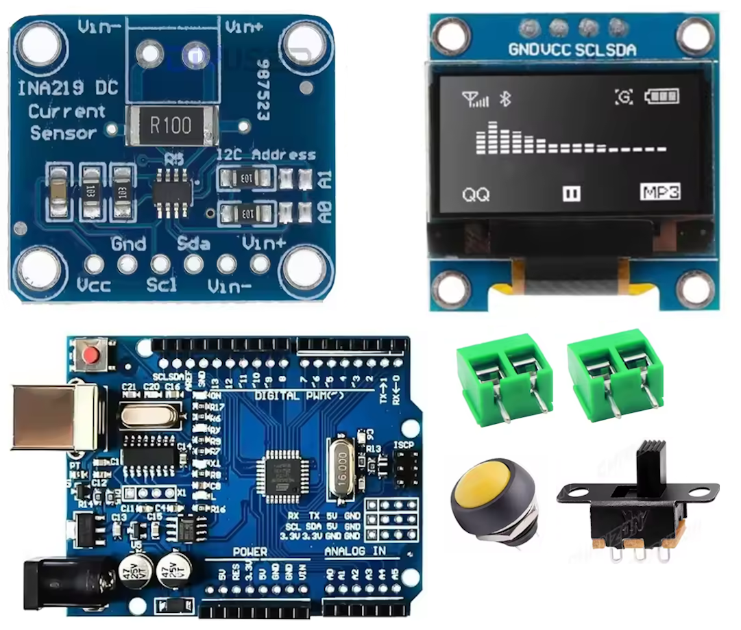
 Arduino
UNO. The project could be done with any MCU - the only requirement
is that it supports an I2C interface. If the MCU did not support internal
pull-ups then a pull-up resistor (eg, 10kΩ)would be required for the
momentary display switch. Note that this version of the UNO has thru-holes
adjacent to each pin, so it would be possible to use the thru-holes to
wire the board directly to the other components. However, for this project
a prototyping board with header pins was used.
INA219 Current/Voltage measurement module (CJMCU-219). The module
is based on the INA219 IC from TI. It includes the I2C interface with
pull-up resistors and a pair of jumpers for choosing an alternate
address. It operates with 3.3V or 5V, but does not have
reverse voltage protection. In the configuration usually supplied
(R100 resistor) it can measure up to 3.6A at 26V.
OLED module, 0.96", I2C. Any equivalent device will work. The
advantage of an I2C display is that it shares the I2C bus already
implemented for the current sensor. 0.96" provides an
easily readable display with the data on two lines on two screens,
selected by a push-button. To simplify assembly, header pins were
soldered to the display module, and a connector used to make the
connection to the other components.
Prototyping board, hookup wire. The board should be sized to be
clear of the USB and power connectors at the end of the UNO, to provide
maximum options for positioning.
LED and matching resistor for 5V (optional).
Connectors:
2x2-pin Screw headers, or any other similar type of bare cable connector,
or socket for use with adapters.
Push-button SPST (on-off) switch, momentary. This switch is mounted on
the faceplate. It is used to temporarily show the alternate
display.
SPDT switch. This switch is optional - it is used to isolate logic
ground from measurement ground (see below).
Schematic
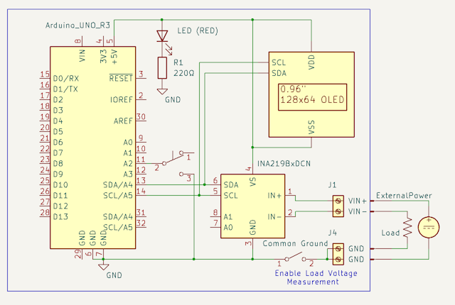
 The
schematic shows the setup for an Arduino, with Ground, +5V and SDA/SCL for
the I2C interface. The INA219 module has IN+ and IN- brought out to one
pair of screw terminals. The other pair is commoned and connected
via a switch to logic ground. Including this switch means that the
load ground can be isolated from the logic ground if needed, while still
using the screw terminals to make the connection between load and power
supply ground. Note that if the power/load ground is not connected
to logic ground then voltage cannot be measured.
The momentary switch is shown connected to A2 - this choice was purely
for convenience and any analog or digital pin could be used, provided that
the appropriate change is made in code. This switch changes the
displayed values between Load Current/Bus Voltage (the default) and
Power/Load Voltage. Note that load voltage is calculated as bus
voltage plus shunt voltage.
The OLED display is wired to the I2C lines in parallel with the INA219
module. The default address for the display is 0x3C and for the
module is 0x40.
The optional power LED is wired across the 5V supply, with a suitable
resistor.
Construction

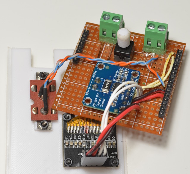
The parts are assembled on a piece of prototyping board. The
prototype was assembled without much regard for space other than matching
the dimensions of the UNO. A UNO protoboard would have worked
just as well. Note that the header pins are modified by
pushing the mounting strip to the end of the pins and then soldering from
underneath - this places the board as close as possible to the surface of
the UNO, minimising the height of the finished assembly. Also, the
proto board can be single-sided and used with the plated side down, so
wires can be run on the unplated side and fed through holes to their
connecting points. This makes for a sturdier assembly. Header
pins are used for only one section on the digital pin side of the UNO, as
the two sets of headers are not spaced apart with standard 0.1"
spacing. If access to the pins D8 to ARef is required then
alternative arrangements must be made.
The INA219 module is then attached with some double-side foam tape, and
the wiring run to the proto board. The screw terminals and the push-button
switch are mounted to the protoboard - some glue has been added for the
screw terminals to ensure the mounting is solid. The wires for the
module IN+ and IN- connections are solid copper, which is actually
overkill for the ~3A maximum current, but using solid wire simplified the
placement of the module. Using 90-degree header pins for the
display module would have permitted a slightly more compact assembly while
still maintaining the convenience of a connector, but in practice the
height of the finished unit is set by the screw connectors on the proto
board.
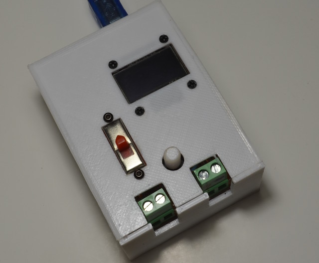
Complete
 The
code uses standard libraries for both the INMA219 and the display, so it
is very simple. The only slightly complex part is formatting the
current and voltage readings to provide large lettering on a 128x64
display while still maintaining a suitable level of precision, given that
current can range from tenths of a mA to Amps.
Upgrade. Having completed the project the posssibility of an
upgrade emerged. The SPST switch that is used to isolate the load
ground from the logic ground could be upgraded to DPDT. The second
pole could be wired with a centre ground and one lead to a UNO GPIO.
This input could then be tested in code to display only the current when
the grounds are not connected (the voltage and power readings fluctuate
randomly when the grounds are not connected). Whether or not this is
worthwhile would depend on how frequently measurement are being made that
require an isolated ground. The logic for this additional GPIO input
would follow the existing logic for the momentary display switch -
configure the GPIO with a pull-up and test for switched to ground when the
load ground is isolated.
Code
Download

 Arduino
UNO. The project could be done with any MCU - the only requirement
is that it supports an I2C interface. If the MCU did not support internal
pull-ups then a pull-up resistor (eg, 10kΩ)would be required for the
momentary display switch. Note that this version of the UNO has thru-holes
adjacent to each pin, so it would be possible to use the thru-holes to
wire the board directly to the other components. However, for this project
a prototyping board with header pins was used.
 The
schematic shows the setup for an Arduino, with Ground, +5V and SDA/SCL for
the I2C interface. The INA219 module has IN+ and IN- brought out to one
pair of screw terminals. The other pair is commoned and connected
via a switch to logic ground. Including this switch means that the
load ground can be isolated from the logic ground if needed, while still
using the screw terminals to make the connection between load and power
supply ground. Note that if the power/load ground is not connected
to logic ground then voltage cannot be measured.
 The
code uses standard libraries for both the INMA219 and the display, so it
is very simple. The only slightly complex part is formatting the
current and voltage readings to provide large lettering on a 128x64
display while still maintaining a suitable level of precision, given that
current can range from tenths of a mA to Amps.