CNC Wireless Link
Peer-to-peer wireless communication for GRBL using ESP_NOW.
A connection from the USB/Serial port of the PC to the
UART port of a CNC machine using ESP_NOW wireless link. It is configured for
plain text (GRBL), but the procedure is similar for any serial control
protocol.
This project uses the ESP_NOW wireless protocol built in to EP8266 and
ESP32 micro-controllers to enable full duplex high speed data
communication between a serial port (or USB-to-Serial adapter) of a PC and
the UART port of a CNC machine. A wireless connection means
that the PC can be located further from the CNC, probably in a cleaner and
quieter environment, without the need for long cables and the associated
risk of data corruption from electrical interference - a common problem
where high-current motors are involved.
Note that WiFi is not recommended for CNC communication because of the
lack of inbuilt error checking. ESP-NOW uses the
802.11b/g/n physical layer but it does not rely on a router or a WiFi
network, it is not subject to the latency of a WiFi network. It uses
SLIP/PPP which is specifically designed for point-to-point serial
communication.
The particular configuration of ESP-NOW is peer-to-peer,
bidirectional. This provides a fast connection with automatic
reconnect and no need for a server or available WiFi. The code is the same
at both ends. The simplest and cheapest ESP device has been used - ESP-01.
Although the project uses a serial port (or serial to USB adapter) at the
PC end, the project runs on any ESP8266 or ESP32, so it could be used with
a development module with an on-board USB port, removing the need for a
USB-to-serial adapter at the PC end. In this case it was used with a
serial port because this port on the PC was otherwise unused and could be
dedicated to the CNC.
Similarly, the UART interface at the CNC end could be removed and the USB
interface of an ESP development board used to connect to the CNC.
Or, the machine to be controlled might be a 3D printer, or plotter.
The wireless communication means it is also very suitable for a robot.
A UART interface for the CNC was used in this case because the port
was already configured for a wired remote control and was therefore very
accessible, and it included a supply voltage. The project also
includes an example of dealing with different logic levels (5V and 3.3V)
between the ESP and the device, which may or may not be required,
depending on the interface.
Parts:
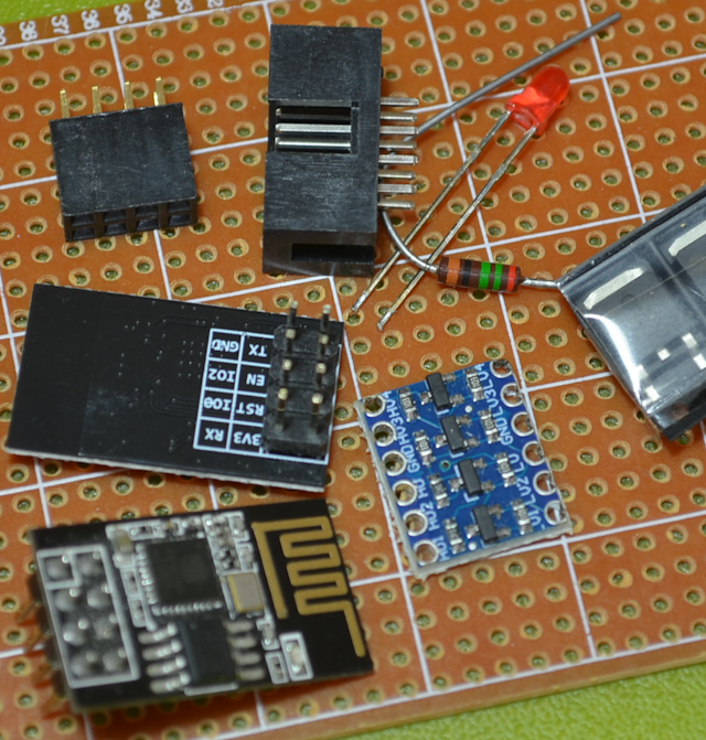 Micro-controllers:
ESP-01 (2 of) In fact, any ESP could be used. The 01 is very
small and very inexpensive, but it does not have a USB port, so it needs a
programmer.It has the advantage of using the readily available 4x2 header
as both a connector and mounting fixture.
Interface board:
Strip prototyping board
AMS1117 3.3V regulator or similar
10-22uF tantalum capacitor
4-channel logic level converter (only 2 channels used)
Hookup wire,
Connectors:
4x2 male header. Used for the ESP-01. If a different ESP is used at the
receiver end the connection will be different.
4x2 female header. Used to connect to an existing manual remote
controller cable. This connection could be different for some CNC
machines.
Optional:
220~250Ohm Resistor
Red LED
Schematic
 The
schematic shows the setup for a 5V TTL level UART interface at the CNC
end, using the remote controller header. This is the
connection used with the RaMPS 1.4 boards and many other CNC machines. It
might apply to other devices such as plotters or 3D printers. This
level conversion would be duplicated if the PC end is a serial port,
unless a separate TTL to Serial adapter is used, but note that a 5V supply
will be needed. Note that Tx and Rx on the male header are labelled
from the point of view of the machine.
The
schematic shows the setup for a 5V TTL level UART interface at the CNC
end, using the remote controller header. This is the
connection used with the RaMPS 1.4 boards and many other CNC machines. It
might apply to other devices such as plotters or 3D printers. This
level conversion would be duplicated if the PC end is a serial port,
unless a separate TTL to Serial adapter is used, but note that a 5V supply
will be needed. Note that Tx and Rx on the male header are labelled
from the point of view of the machine.
The suppression capacitor for the AMS1117 can be anything from 10uF to
22uF, but it should be tantalum. The AMS1117 should regulate down to
about 4.5V. If the 5V supply is unreliable then a smoothing
capacitor may be required. This should be as close to the AMS1117 as
possible.
This project does not show the setup for the PC end of the link.
Alternative options for the PC end are:
- An exact duplicate of the CNC end, connected
to a serial port of the PC. Five volts will be required for the regulator
and logic level shifter.
- A duplicate of the CNC end connected to a serial-to-USB adapter and
connected to a USB port of the PC. Logic level shifting may not be
required if the adapter serial interface is 3.3V. This is the arrangement
used in this project.
- Any model of ESP that has a USB interface. Connect the ESP
directly to the USB port of the PC.
Communication between the MCUs is ESP-NOW, and from each MCU to its host
is the inbuilt UART port.
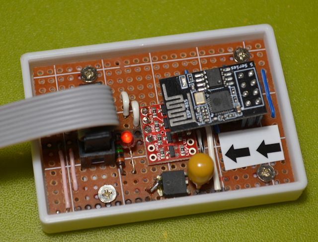
Construction
The parts are assembled on a piece of strip prototyping board. The
prototype was assembled without much regard for space, so with some
redesign it could be made much smaller. If it is going to be
enclosed in a case then it might be preferable to use a 90-degree header
for the CNC cable end, so that it can be mounted flush with one end rather
than sunk below the top surface.
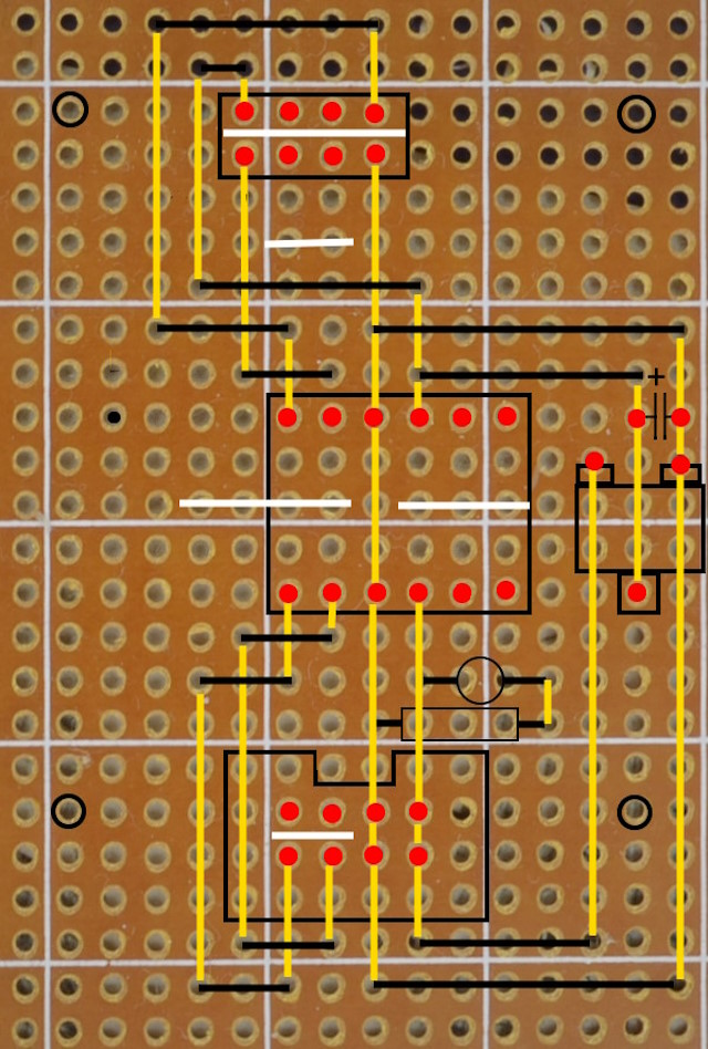
The diagram shows the wiring side with the copper traces running
vertically. The white stripes represent the traces that must
be cut on the underside of the board. The black lines are the links to be
inserted, while the yellow stripes are the copper traces as actually used
in the circuit. The image indicates that some traces (eg, GND and
VCC) have been marked on the upper surface - this marking helps to
minimize confusion that can be created by continually turning the board
over between placing connecting wires and doing the soldering.
Note that the logic level converter layout is not standardized and some
modules may have a different layout.The regulator used in this example is
a SMD device, but it is compatible with a thru-hole board if the tabs are
bent down and a short length of wire is used to stake the tab through to
the track.
The ESP-01 header is not keyed so the board should be marked to make the
required orientation obvious.
Complete
 The
code turned out to be somewhat more complex than expected. The basic
process - receiving from the serial port, sending via ESP_NOW and vice
versa - is fairly simple, but there are a few complicating
factors.
The
code turned out to be somewhat more complex than expected. The basic
process - receiving from the serial port, sending via ESP_NOW and vice
versa - is fairly simple, but there are a few complicating
factors.
In GRBL, the unit of data that is handled as a single message for
purposes of sending and receiving is a line. However valid line
endings are different between the host and the device. For messages
sent from the host to the device the line ending is always carriage
return/line feed ('\r\n'). Responses sent back from the machine to
the host can only have a single line terminating character, either
carriage return ('\r') or line feed ('\n'). Most machines use
carriage return, but line feed should be allowed for. This
variability complicates the process of detecting the end of a line of
commands. To avoid running different code at different ends of the
communications link, the message should be sent exactly as
received. The code uses a method whereby a carriage return or
line feed will be flagged as the end-of-line marker, but there is a check
to see if a line feed follows a carriage return or a carriage return
follows a line feed. The result of this check then controls the line
tremination character(s) appended to the received text when it is passed
through.
In addition, there are several commands that can be sent from the control
program that are a single character without a line terminator. There
are some single character commands that are ASCII values - these are
handled as special cases. Other single-character commands have values
greater than 127 and are simply passed straight through. These commands
may be may be difficult to enter into a terminal program. There is one
command - '\0x18' - that may be useful for testing purposes so a small
routine that converts '$X' into 0x18 was created. If testing does not
require this code to be used, or if it can be handled as 0x18 from the
test application, then this piece of code can be deleted. Alternatively,
the routine can be copied and modified to handle additional
single-character commands. The receive buffer is not
cleared when a single-character command is received, so the data stream
will continue to fill the buffer with a valid command. Whether or
not this command is subsequently executed depends on the action taken in
response to the single character command. For instance the speed
overrides should not ignore the current message but an emergency stop
obviously will.
Because GRBL uses a mixture of control codes and plain text it is a
useful case for this example. Protocols that use either only control
codes or only plain text would be implemented by removing the unused data
handling.
There are plenty of debug statements left in the code if anyone runs into
problems with a particular system.For this project a breakout was
constructed for the CNC end of the link so that the data could be
monitored as it was sent and received. It was also very useful to
include OTA in the uploaded code so that it was not necessary to
disconnect then reconnect ESP modules whenever new code was uploaded.The
code fits in the original 0.5MiB ESP-01, although the 1MiB ESP-01 is more
readily available and probably no more expensive than the smaller model.
No allocation for a file system is required.
Code
Download
